MAKE A MEME
View Large Image

| View Original: | FlCirc.PNG (432x360) | |||
| Download: | Original | Medium | Small | Thumb |
| Courtesy of: | commons.wikimedia.org | More Like This | ||
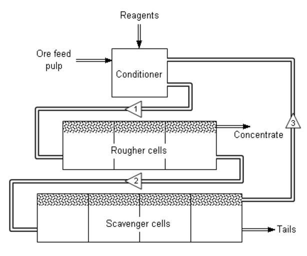
| Keywords: FlCirc.PNG Simple flotation circuit for mineral concentration Numbered triangles show direction of stream flow Various flotation reagents are added to a mixture of ore and water called pulp in a conditioning tank The flow rate and tank size are designed to give the minerals enough time to be activated The conditioner pulp 1 is fed to a bank of rougher cells which remove most of the desired minerals as a concentrate The rougher pulp 2 passes to a bank of scavenger cells where additional reagents may be added The scavenger cell froth 3 is usually returned to the rougher cells for additional treatment but in some cases may be sent to special cleaner cells The scavenger pulp is usually barren enough to be discarded as tails More complex flotation circuits have several sets of cleaner and re-cleaner cells and intermediate re-grinding of pulp or concentrate own 2006-10-23 Thermbal wikipedia en Thermbal Original upload log en wikipedia FlCirc PNG 2007-12-30 14 34 Karlhahn 432×360× 4622 bytes <nowiki>Crop away blank areas</nowiki> 2006-10-23 03 52 Thermbal 669×438× 11504 bytes <nowiki>Drawing I created myself by using Excel Nothing taken from any other source Uploaded by Thermbal </nowiki> Flotation Diagrams | ||||