MAKE A MEME
View Large Image
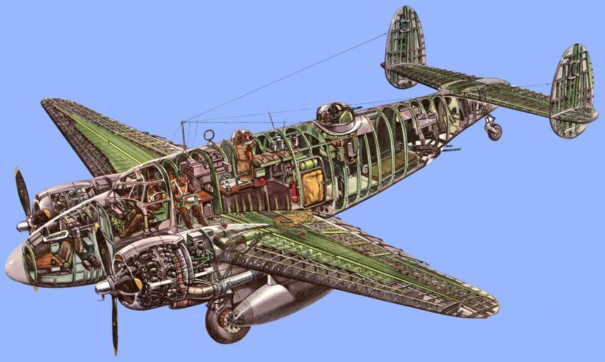
| View Original: | Design_Analysis_of_the_Lockheed_PV-1_Ventura.png (1676x1004) | |||
| Download: | Original | Medium | Small | Thumb |
| Courtesy of: | www.flickr.com | More Like This | ||
| Keywords: By Wilfred N Wallace Staff Engineer Lockheed Aircraft Corporation The PV-1's primary characteristics of speed, maneuverability, stamina, make it a versatile plane that lends itself to a variety of global tasks Little publicized, yet doing one of the war's outstanding jobs, the twin-engine Lockheed PV-1 Ventura is a versatile, high speed airplane for which our Navy is finding extensive use in a multitude of important purposes. Principally a low altitude performer, Ventura does medium-range patrol bombing, anti-submarine work, photo reconnaissance, land bombing and even fighter combat duty. Its high performance, maneuverability and rugged construction, makes it an ideal craft for any military service demanded of it commensurate with its design limitations. In addition to its normal complement of armament which can be used against enemy aircraft or for strafing, PV-1 carries six 325-lb depth charges that may be dropped simultaneously or selectively. Furthermore, two 500-lb bombs or two depth charges may be substituted for the droppable fuel tanks. Alternate cargo that may be carried is one 2000-lb torpedo, or six 500-lb bombs for glide or skip bombing. Accommodations are provided for a crew of four to six with a single flight station; dual controls are available if required. The wing group comprises a center section joined to the fuselage to form an integral part, two outer panels, and two wing tips. All span-wise wing skin joints ahead of the 30% chord point are of the butt type, and flush skin rivets are used throughout. Leading edges between the sides of the fuselage and the nacelles are attached with piano hinge for ready access to plumbing lines and controls. Principal structural members in the center section are a main beam and front and rear shear beams. These beams are interconnected by formed sheet metal ribs and covered on the top surface with corrugation reinforced .040 24ST Alclad skin from the fuselage line to the center section extremity. The lower surface is principally stressed removable panels for access to the fuel cells. This bottom surface is composed of stringer reinforced .040 24ST Alclad skin. The main beam carries continuously across the fuselage with one piece upper and one piece lower beam caps of pi-section extruded 24ST aluminum alloy. In the portion of the beam that carries through the fuselage, the web is of truss type construction with I beam and channel sections gusseted to the beam caps. From the fuselage line to the outboard wing attachment rib, the main beam is of box type construction with webs of .064 to .125 24ST Alclad sheet stiffened by angles extending from cap to cap. Center section front and rear shear beams have extruded T section caps and single webs stiffened by vertical angles. These beams are not continuous through the fuselage but attach to connecting members of the fuselage line with bolts and splice plates. At the point of outboard wing panel attachment, main beam fittings are forged SAE-4140 steel lugs bolted to the beam caps. These lugs engage U-type forged 4140 steel fittings similarly attached to the main beam of the outboard panel, and are bolted through with close tolerance bolts lying in a vertical axis. The center section rear shear beam is attached to the rear beam of the outboard panel by a row of bolts through the respective webs and by single shear bolts through the beam cap members in a horizontal axis. The outboard panel attachment is completed structurally by a skin and corrugation attachment completely around the periphery of the airfoil section using flush head screws. Main landing gear pivot fittings consist of two aluminum alloy forgings which are bolted to the center section structure on the aft side of the front shear panel. These fittings also provide the lower points of attachment for the engine support bay. This support bay consists of a non-heat treated X4130 welded tubular structure that carries the engine loads from the engine mount attachment at the firewall back into the center section proper. Also part of the center section, the nacelle fairing aft of the firewall is made of an upper and lower section plus a section to complete the lower nacelle line, which is attached to the flap. Both the upper and lower sections are attached to the center section by rivets, Hush screws, and stop nuts. The lower section provides an enclosure for the retracted landing gear. It is built around 5 bulkheads covered with skin and stringers which provide the side structures to which the landing gear doors are attached. Outer wing panel framework consists of a main beam, an auxiliary rear beam, and formed sheet metal ribs. These ribs are, for the most part, .032 24ST Alclad. Ribs that forms the auxiliary fuel tank bay are .040, and the last six ribs toward the tip are made of .025 material. 24ST Alclad skin ranging from .025 to .032 in thickness covers both top and bottom of the outboard wing panel. The leading edge skin section is .040. The upper skin is reinforced with a combination of .040 corrugations and stringers, and the lower skin is reinforced by stringers alone. Upper and lower caps joined by a single web form the main beam of the outboard panel. The caps are made up of three segments joined by splice plates and vary from an extruded T section near the root end and extruded angles in the midsection to formed sheet metal angles near the tip. Between each rib station, the web contains round access holes and is stiffened by flanged rings riveted to these holes and by vertical stiffeners that serve as rib attachments. The rear beam of the outboard wing panel is two separate assemblies. The inboard section completes the wing shell by closing off the structure ahead of the wing flap, and extends from the root to the first rib station outboard of the flap. This section of the rear beam is .051 24ST Alclad with formed flanges for caps. Beginning at the wing flap, the outboard section of the rear beam extends to the tip rib. It does not tie directly to the inboard section since it is located approximately 10" further aft at the rib bay where the two sections overlap. The loads are carried at this point through the surface structure and the ribs. The outboard section of the rear beam is .040 24ST Alclad with the edges flanged to form the beam caps. This section completes the wing shell structure ahead of the aileron and carries the aileron by a full-length piano hinge. Four leading edge slots are located near the tip on the outboard wing panel, and one leading edge slot is located in the wing tip section. These slots insure smooth airflow and effective aileron control at high angles of attack. At the points of attachment of the droppable fuel tanks, machined fittings and heavy tubes have been incorporated in the internal structure of the outboard wing panel, and a doubler plate has been added to the lower exterior surface to take the external fuel tank loads. Still further outboard, an adapter plate curved to fit the contour of the wing is bolted through the outer left wing surface to provide a mounting for a torpedo training camera. The wing tip frame consists of four .025 24ST Alclad flanged members running in a lateral direction, and three .020 flanged ribs that are cut out for the spar members. The tip is covered with .020 skin; and is attached to the outboard panel with a row of screws and stop nuts around the periphery of the tip rib. One navigation light is mounted to the outermost end of the tip. Ailerons: —Aileron construction consists of a spar of .025 24ST Alclad with formed flanges, ribs of formed .025 sheet, and is covered with fiat skin of .020 24ST Alclad. Numerous access holes sealed with cloth patches are provided in the spar. A continuous piano hinge is located on the upper flange of the spar, and the gap formed by the upward moving aileron is closed by a curved extension of the lower skin. The aileron clevis horn is an aluminum alloy casting, as are the aileron balance weight brackets. Of internal type, the balance weights extend from the aileron spar forward through the rear beam of the wing panel at approximately mid-point of the aileron span. They provide a static balance of 100% and a dynamic balance coefficient of -.016. Each aileron is equipped with a trim tab which is attached by a piano hinge to a supplementary beam of the aileron. The tabs are of frame construction similar to the aileron, and are covered with a formed metal skin. The right aileron tab is a balance tab only. Its setting may be changed only on the ground by means of an adjustable push-pull rod attached to a stationary fitting. The tab on the left aileron is a combination balance and controllable trim tab. It is operated through an adjustable push-pull rod attached to a tab control unit and is controllable from the cockpit. Wing Flaps: —Wing flaps are located in the wing outboard of the fuselage and are of the Lockheed Fowler type. They cover approximately 34% of the wing span, and have a total angular movement of approximately 37° and a total linear movement of approximately 36". Since this type of flap extends the actual wing area as well as increasing the lift coefficient, they permit relatively slow landings for a highly wing loaded airplane. With the flaps partially extended, an increase in lift is obtained with a minimum increase in drag. In this position, the flaps improve take-off distance over an obstacle. Actually, the flap is a miniature wing in construction, and each unit is composed of four sections which are bolted together. Each section has a main beam of flanged .051 24ST Alclad, formed ribs of .020 to .032 material, and is covered with .020 upper and .032 lower skin of 24ST Alclad reinforced with .025 sheet metal angles for stringers. Between the sections and at each end of the flap is attached a ball bearing roller flap carriage upon which the flaps are supported. The flap carriages operate on extruded aluminum alloy tracks which are constructed as a part of the reinforced training edge ribs of the wing and are attached to the rear shear beam of the center section and outer wing panel. The flaps are operated by attached cables which in turn are actuated by a hydraulic cylinder. Fuselage Fuselage is a semi-monocoque structure covered with 24ST Alclad sheet in thicknesses varying from .025 to .051. It is characterized by a relatively deep cross section in comparison to the width which permits carrying the bomb load entirely beneath the floor. Transverse members of the structure are 24ST Alclad bulkheads and frames. Plastic forms the shape of the nose section. The entire skin of the fuselage is flush riveted except under fillets and on the gun blast protective sheets at the turret. Vertical skin joints forward of the pilot's compartment are butt joints with an .051 24ST Alclad doubler underneath. All other skin joints lap down and aft on the outside. Principal bulkheads have the following locations: a bulkhead at station 92¾ forms the aft wall of the control tunnel; a solid bulkhead at the front wing beam, station 147, is just aft of the pilot's compartment; a bulkhead at the main wing beam, station 188, is just forward of the fuselage cabin; bulkheads at stations 236 and 259 are just forward and aft of the navigator's hatch; the bulkhead at station 311 is in the middle of the cabin door ring; a bulkhead at station 360 is on the centerline of the turret; two bulkheads at stations 522-1/8 and 561 form the stabilizer attachments. Hat section longerons are the main fore and aft load carrying members of the fuselage. Extending from approximately the midpoint of the center section attachment, the upper hat sections run back to the forward end of the stabilizer attaching point. The lower hat sections run from the forward wall of the bomb bay to a point slightly aft of the forward end of the stabilizer attaching point. Cutouts in the bulkheads for these hat sections are bridged by an .064 plate riveted to the hat section longerons. Keelsons are the longitudinal members at the bottom of the fuselage, parallel and equally distant from the centerline of the airplane on both right and left sides. They are replaced by the floor and the bomb supporting structure between the forward wall of the bomb bay and a point just aft of the forward edge of the turret station. Floor and bomb bay support structure is a network made up of longitudinal and transverse channels joined top and bottom at each intersection by riveted gusset plates. The channels are all 4" deep and a stressed skin surface riveted to the bottom of the channels forms the top of the bomb bay. This assembly of floor channels is riveted to the lower longitudinal hat section members on each side of fuselage. The pilot's escape hatch is located above the flight station and can be released in an emergency by pulling down on a red handle overhead and in the center of the compartment. A navigator's hatch on top of the fuselage aft of the radio compartment can be used as an exit in emergency if the four knobs are unscrewed and swung out of the way and the hatch pulled down into the cabin. The main cabin door is located on the left side of the fuselage, and an emergency release with handles in the flight compartment, navigator's compartment, and radio operator's compartment, is provided for jettisoning the door in case of an emergency. A camera side door is on the left side of the fuselage aft of the main cabin door. It is a circular door which may be completely detached by turning a knob and pulling it out of the lower attaching fittings. A reconnaissance flare chute door is in the right rear side of the fuselage bottom and may be operated by a lever at the side of the flare chute or by a remote control in the pilot's compartment. Each of the two bomb bay doors consists of an upper and a lower panel made of formed .025 24ST Alclad sheet stiffened by ribs and stringers. The lower panels are attached to the upper panels by five hinges, and these in turn are hinged to the fuselage with six hinges. When closed, the door assemblies on the right and left sides meet at the centerline of the airplane to complete the fuselage contour. Three sets of triangular trusses for each door assembly extend from carriages on tracks attached to bulkheads in the bomb bay and are attached to the bomb bay door lower panels. When the doors are opened, the trusses push the lower panels laterally outboard and in so doing they fold against the upper panels, pushing them up and out. The door truss carriages are moved by cables, which in turn are attached to the hydraulic actuating cylinder. The tail cone serves as a housing for the tail wheel when it is retracted and the tail wheel doors form a part of the tail cone assembly. These are operated by a link attaching to the tail wheel pivot pin. When the tail wheel is fully down, the doors close and the two small spring loaded auxiliary doors provide clearance for the tail wheel strut. Empennage The PV-1 empennage is of metal construction throughout. All exterior surfaces are flush riveted. Controllable trim tabs are provided on the two rudders and elevators. Fin and rudder assemblies may be used interchangeably on the right or left sides, and stabilizer nose sections may likewise be interchanged between the right and left stabilizer panels. The elevator center section or tail flap moves up with the elevator and rests on the tail cone when the elevators are in the down position. Seven removable sections compose the stabilizer: a center section, a left and right panel, two leading edges or nose sections, and two tips. Panels and the center section are of similar type construction. Panels have .051 24ST Alclad front and rear spars interconnected with formed ribs varying from .025 to .064 in thickness and covered with stringer-reinforced skin of .020 and .025 24ST Alclad. Each of the panels has an elevator tab control unit mounted between two ribs close to the rear spar and a rudder control casting assembly installed at the extreme outboard end of the rear spar. Formed .032 material is used for the center rib and .040 for the skin gage. The stabilizer center section is bolted to the fuselage through extruded angles at the fuselage line and to the two fuselage bulkheads that lie directly under it. The panels are bolted to the center section through splice plate doublers on the top and bottom skin and on the spars. Stabilizer tips consist of formed .020 24ST Alclad skin covering a framework of five lateral bulkheads and two ribs that are completely cut out for the bulkheads. Ribs and bulkheads are .020 24ST Alclad and the tip is at- tached to the stabilizer panel by screws and plate nuts. Stabilizer nose section is made of .032 24ST Alclad skin riveted and spotwelded to .040 formed ribs. The nose section is attached to the panels with piano hinge at the upper and lower flanges of the front spar for quick removal and access to the control cables for the rudder and rudder tabs which are routed inside the nose section along the leading edge of the panel. Control cables for the elevator tab units are routed through the center section of the panels. At the trailing edge of the stabilizer, two elevators are attached with six cast aluminum alloy ball bearing hinge brackets on each stabilizer panel. The elevators are interconnected and operated as a unit by a single torque tube bolted to the inboard ribs. A cast aluminum alloy control mast is riveted to the torque tube. Each elevator consists of .032 24ST Alclad flanged spar, formed ribs varying from .064 inboard to .020 outboard and covered with .016 and .020 24ST Alclad skin stiffened by .025 drawn channel section stringers. A tail flap built of two wedge-shaped sheet metal ribs interconnected by corrugation reinforced sheet metal skin is installed between the two elevators to increase the up elevator effectiveness. The tail flap is mounted to guide channels fitted around the elevator torque tube near its ends. Tapered sheet metal channels riveted to the outboard edges of the tail flap skin extend over the inboard edges of the skin of the two elevators so that the tail flap is lifted with them whenever the elevators are raised above neutral position. Two elastic bungee cords hold the tail flap down against the tail cone or against the elevators if they are above neutral position. Fin structure consists of four vertical spars of .040 and .051 24ST Alclad, eight sets of formed horizontal ribs of .032 and .025 24ST Alclad, and is covered with .025 skin which is made in halves and riveted at the leading edge to a formed doubler. Where the spars do not extend the entire height of the fin, their line is continued with stringers. Rib assemblies consist of independent segments between the spars. The fins are built in upper and lower sections which are mounted separately to the top and bottom surfaces of the stabilizer panels by means of bolts through curved attaching angles and skin doublers. In the upper section of the fin, three cast aluminum alloy ball bearing hinge brackets support the upper section of the rudder, and the lower fin section carries two similar hinge brackets for the lower section of the rudder. A rudder trim tab control unit is contained in the upper sec- tion of the fin. Rudder construction is similar to that of the fin, with two vertical spars of .040 and .025 24ST Alclad, two intermediate sets of vertical stringers, eleven sets of horizontal formed ribs varying from .025 to .040 in thickness, and is covered with .020 24ST Alclad skin. Each rudder assembly consists of an upper and a lower section which are joined only at the hinge line by bolting to a short torque tube that comprises the rudder mast. Each rudder is statically balanced by a section of the rudder housing balance weights that extends forward of the hinge line near the top of the upper rudder section and a similar balance section at the bottom of the lower rudder section. These balances also provide a dynamic balance coefficient of -.0046. Each of the four empennage trimming tabs is composed of a formed sheet metal spar to which wedge-shaped sheet metal ribs are riveted and over which is riveted a sheet metal skin. The tabs are attached to an auxiliary tab spar in each of the major control surfaces by continuous piano hinge. Landing Gear Main landing and tail gears are both single strut, fully retractable type. The main wheels retract into the engine nacelles and are enclosed by flush-type doors when retracted. The tail wheel likewise is enclosed by flush-type doors when retracted. Both main and tail gears are retracted and extended hydraulically. The main landing gear is interchangeable between right and left sides of the ship with minor adjustments. Each main gear has a single oleo shock absorber strut mounted in a forged aluminum alloy fulcrum which hinges on the forged aluminum alloy pivot points that are bolted to the wing center section. The strut is mounted toward one end of the fulcrum and is braced against side loads by a single tubular steel strut extending from the other end of the fulcrum to approximately the midpoint of the oleo strut. A cantilever type axle is mounted on the oleo strut, and two pairs of torque links are employed to carrying the torsion loads from the cantilever axle into the strut barrel. A two-place tubular steel drag strut braces the main landing gear fore and aft loads, and the hydraulic actuating cylinders fold the drag strut to accomplish retraction. Hydraulic locks secure the gear in the extended or retracted positions. Main landing gear wheels are of magnesium alloy and are fitted with hydraulically operated multiple-disc type brakes. Tires are 16.00 X 16 and are 12-ply heavy duty type. The tail gear assembly includes an oleo shock absorber strut and a forged aluminum alloy wheel fork. A 17" smooth contour type tire is used. The assembly is hinged directly to the tail bulkhead of the fuselage and at approximately the midpoint of the oleo strut. A hydraulic actuating cylinder attached to the top of the oleo strut and to a point in the fuselage slightly offset from the hinge axis retracts or extends the gear. Mechanical locks secure the shock absorber in the retracted and extended positions. The tail gear uplock consists of a spring loaded latch attached to the fuselage which engages two roller bearings attached to the upper end of the shock absorber. Normally, the initial 7/8" extension of the retracting cylinder re- leases the up-lock. An emergency manual extension control is provided consisting of a cable which rotates an arm on the upper end of the shock absorber which moves the actuating cylinder piston rod in the manner normally done by hydraulic pressure. The tail gear downlock consists of a spring loaded pin on the upper end of the shock absorber strut which engages a slotted steel casting attached to the fuselage structure. The initial 7/8" retraction of the hydraulic cylinder releases the downlock pin. Incorporated in the tail gear assembly is a friction shimmy damper and an anti- swivel lock which is controlled by the pilot. This lock is cable operated by a lever mounted on the pilot's control stand and consists of a spring loaded pin attached to the oleo strut cylinder barrel that engages a hole in the upper tail wheel torque link collar. Power Plant Power is supplied by two Pratt & Whitney 18-cylinder Twin Row [Double Wasp —Ed.] engines of the R-2800-31 series. With a total of 4000 hp power loading is 6.63 at a normal gross weight and 7.75 at overload gross weight. The engines are equipped with a single-stage, two-speed supercharger and a pressure injection type carburetor with an automatic altitude compensating mixture control. Propeller gear ratio is 16:9. A Hamilton Standard Hydromatic full-feathering, wide-blade propeller is used, the blade design being pioneered on the Ventura model and results from study and tests to obtain efficient small-diameter propellers that would produce the most desirable takeoff and climb characteristics. Use of this blade design with a relatively small diameter of 10' 7" has permitted a nacelle location close to the fuselage with minimized single-engine yawing characteristics. Each engine is bolted to a welded steel tubular type engine mount through vibration absorbing bushings. These flexible mounts are of a sandwich type construction of alternate layers of synthetic rubber and metal. They are so arranged that the movement of the engine is about an elastic center and close to the center of gravity of the entire sprung weight including the engine, cowl, propeller, exhaust collector, and engine driven accessories. Forked fittings are provided on the engine mount for attachment to the engine support bay at the firewall. Connection to this structure is made through bolts in shear. The axis of these bolts is normal to a line drawn radially from the center of thrust so that the bolts are not subjected to shear loads imposed by torque reactions of the engine. The firewall is a bulkhead of corrosion resistant sheet steel or AMS 5040 steel, and each engine and its accessory components comprise a unit removable at the firewall for service operation. Each unit is interchangeable except for minor variations in the positions of the accessories and their plumbing. Engine Cowling Engine and accessory cowling is of a conventional type consisting primarily of an NACA type engine cowl and removable panels over the accessory section. The cowl is divided into three major groups: the nose cowl, the intermediate panels or removable skirts, and the engine cowl flaps. Five formed sheet aluminum alloy segments are riveted and spotwelded to make the nose cowl which is attached to the rocker box lugs on the front row of engine cylinder heads. The nose cowl attachment consists of 16 aluminum alloy castings riveted to the nose cowl and carrying vibration absorbing bushings which are attached to the rocker box lugs by an extruded link assembly. Intermediate cowl panels are formed of aluminum alloy sheets reinforced at the edges by doublers. Forward edges of the intermediate cowl panels are attached to the aft edge of the nose cowl. Aft edges of the intermediate panels are attached to a support ring secured to the rocker box lugs on the rear row of cylinder heads. Arrangement of these panels is such as to permit quick removal of any panel without disturbing either of the adjacent panels. They are secured throughout with dowel pins and Dzus fasteners. Cowl flaps are mounted on the same rear ring to which the intermediate panels are attached. Cowl flaps on each side of the engine are divided into two sets, four flaps in the upper set and three in the lower. The individual flaps in each set are fabricated from stainless steel and consist of a torque tube, ribs, and flap skin. A universal joint attachment is used to join the flaps together, and all flaps in a set, except the master drive flaps, are driven from the adjacent flap through these universal joints. Each set of flaps is operated by a screw jack actuating unit mounted on the rear cowl support ring. A bracket located between the two upper engine mount tubes supports the two cowl flap motors. Each motor drives the two sets of flaps on its respective side of the engine through flexible torque shafts. The induction system consists primarily of three parts, two of which are integral with the cowling. The entrance scoop is a part of the fixed nose cowl and carries a coarse mesh screen over the opening. Immediately aft of the screen a hole has been provided in the fixed nose ring to maintain a source of air in event that the screen becomes iced over. The second part of the induction system is a duct integral with the removable intermediate cowl panel at the top of the engine. The third part is a carburetor air elbow which incorporates a valve for closing off the flow of cold air and admitting warm air from underneath the cowling. This elbow is attached rigidly to the engine cowling and flexibly attached to the carburetor by a synthetic rubber boot. The valve or alternate air door is controllable from the pilot's station and is locked in the full hot and full cold positions by means of a linkage provided in the control system. Engine accessory cowling consists of a stainless steel exhaust collector well, a diaphragm seal plate, an exhaust collector fairing shroud, and aluminum alloy cowl panels. The exhaust collector well and diaphragm seal plate are attached to the engine mount ring, and the inner surface of the diaphragm seal plate is provided with a flexible sealing material of woven asbestos impregnated with neoprene. This sealing material bears against another plate attached to the engine and provides a seal between the power section and the accessory section. The exhaust collector fairing shroud is attached to the outer surface of the exhaust collector well and extends forward under the cowl flaps and over the exhaust collector providing a smooth surface and an efficient aerodynamic shape for the cooling air outlet. Accessory section cowl panels are attached to the outer surface of the exhaust collector well and to the firewall by Dzus fasteners. Incorporated in the lower cowl panel is the entrance duct to the oil cooler. The exit "Y" duct for the oil cooler is permanently attached to the firewall and nacelle structure. Exhaust System The engine exhaust system consists of a collector ring composed of eight tubular sections clamped together with slip joints between each two cylinders to form a manifold and a single outlet on the outboard side of each nacelle. Each section is removable without disturbing other sections. The entire collector ring is supported from the stub stacks from the rear row of cylinders. Service stacks from the front row of cylinders are shrouded and connected at both the fore and aft ends by slip joints with a support at the aft end to prevent excessive end play. The exhaust tailpipe is attached to the outlet "Y" of the collector ring by means of a slip joint and is further supported at the aft end by a support brace extending from an accessory drive pad on the engine. An exhaust flame damper is provided for each engine exhaust tailpipe. This flame damper is a readily removable installation and consists of a cold air intake, mixing chamber, and a flame suppressor. It is furnished as an alternate load item. Oil System Each engine is provided with its own circulating oil system complete with a pressure pump, scavenging pump, oil cooler, and tank. These are the normal operating systems. There is no connection between them, and each is identical to the other. In addition, a storage and transfer system is provided which supplies extra oil to the service systems on flights of long duration. The nacelle oil tank is of welded .051 3SW aluminum alloy construction covered with self-sealing "Armorite." It has a capacity of 15 gal, and contains a warmup hopper. The filler neck is a pneumatic standpipe arranged to prevent overfilling the tank, and the main oil outlet has a small standpipe so that the oil supply within the tank can never be completely exhausted by the engine oil pumps. This leaves a supply of oil for propeller feathering purposes even though there is insufficient oil remaining for engine lubrication. A 14-in diam oil cooler is mounted below the engine accessory section and is supported by the cast magnesium alloy brackets which are attached to the two lower engine mount tubes through vibration absorbing bushings. It is equipped with a thermostatic oil temperature control valve, and the amount of air flowing through the oil cooler is controlled by doors a the aft end of each oil cooler exit duct. The doors are opened or closed by an electric motor operating a jack screw through self-contained reduction gears and located near the bottom on the forward side of the engine firewall. Plumbing in the oil system is 52SO aluminum alloy tubing. Main oil lines are ¾-in diam by .040 wall thickness. An oil drain "Y" valve is provided between the oil tank outlet and the oil-in connection on the engine. The oil drain "Y" oleo serves as the point for admitting raw gasoline to accomplish oil dilution. Gasoline is obtained from the pressure outlet on the carburetor and oil dilution is controlled by a solenoid operated valve. The reserve oil system consists of a 40-gal oil tank installed in the cabin aft of the rear shear beam on the lefthand side of the airplane, a wobble pump located on the aft face of the rear shear beam, and two valves for controlling the oil supply to the nacelle tanks. By opening either valve and operating the hand pump, oil is pumped to the corresponding nacelle tank. Made of welded aluminum alloy, the reserve oil tank is non-self-sealing although it is covered with lagging material to reduce congealing of oil in the tank in cold weather. Fuel System Two separate branches comprise the main fuel system: one branch supplies the port engine, and the other branch supplies the starboard engine. The principal tanks for each branch are located in the wing on the same side as the engine to be fed. They consist of a front main tank and a rear main tank located in the center section, and an auxiliary tank located in the outboard wing panel. Two cabin tanks are also installed, and each normally feeds both engines through the transfer valve. For long range missions, two external droppable wing tanks are provided which tie directly into the left and right branches of the fuel system. For long range ferrying, two bomb bay tanks are installed which feed both engines through the transfer valve. Provisions are also made to connect two additional tanks to the transfer valve. These tanks are not a factory installation but may be temporarily installed in the turret for extreme long range ferrying. A booster pump is mounted in each front main tank and is enclosed in a surge chamber which serves to maintain constant fuel supply to the booster pump when the ship is maneuvering. The front main tanks are the only two tanks that normally supply fuel directly to the engines. These tanks contain a float-operated liquid level maintainer which controls the transfer pump. This float-operated control and the transfer pump comprise an automatic electrical pumping system which maintains the fuel level in the front tank constantly between 75 and 100 gal. Selector Valves Selector valves for each branch of the main fuel system govern the flow from the rear main tanks, the auxiliary tanks, and the external droppable tanks so that fuel may be drawn from any one of these tanks by the transfer pump to maintain the level in the front main tank. In the same manner, the transfer valve controls the flow of fuel to the front main tanks, the forward and aft bomb bay tanks, and the turret tanks when they are installed. The transfer valve may also be used to crossfeed by a setting which allows fuel from the wing tanks of one branch of the main system to flow to the opposite engine. Wing tanks of the main fuel system are of the self-sealing type, as are the two cabin tanks. The bomb bay fuel tanks are a temporary installation and normally are non-self-sealing. They are made of aluminum alloy sheet and are of conventional riveted and welded construction. The droppable external wing tanks are non-self-sealing and are of welded steel construction. All of the tanks except the external tanks are vented to the wheel wells. The external fuel tanks are vented through an internal line which discharges on the lower surface of each tank. aircraft wwii drawings harpoon lockheed ventura rendering pv1 wilfrednwallace | ||||