MAKE A MEME
View Large Image

| View Original: | Coiningpress1.jpg (187x375) | |||
| Download: | Original | Medium | Small | Thumb |
| Courtesy of: | commons.wikimedia.org | More Like This | ||
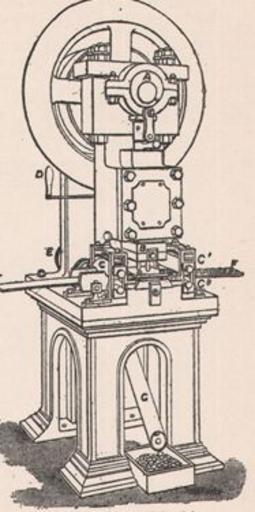
| Keywords: Coiningpress1.jpg Image of a coining press used in mints The blanks are converted into coin by receiving an impression from engraved dies Each blank is placed on the lower of two dies and the upper die is brought down forcibly upon it The pressure causes the soft metal to flow like a viscous solid but its lateral escape is prevented by a collar which surrounds the blank while it is being struck The collar may be plain or crenated milled or engraved with some device In the last case the collar must be made in two or more pieces as otherwise the coin could not be removed without injury The collar for striking English crown pieces is made in three sections now that raised lettering is put on the edge of the coin Sunk letters such as occur on the edges The image shows the press in use at the Royal Mint since 1882 The lever M worked from the front of the machine causes the flywheel to be connected with the driving-wheel and the machine starts The blanks are placed in the slide J and the lowest one is carried forward to the die in two successive movements of the layer-on K a rod working backwards and forwards on a horizontal plate and actuating the finger L fig 8 The lower die is firmly fixed to the bed of the machine and the blank is placed exactly upon it The collar A' is then raised by the lever G so as to encircle the blank and the upper die which is held at A is brought down This is done by the little crank B on the axle of the fly-wheel acting through the rod C and the bent lever D which forms a toggle-joint at E with the vertical piece of metal below it The straightening of the togglejoint when C is pushed forward forces A down to strike the coin The reverse movement of D lifts up the upper die and the collar drops simultaneously so that its upper surface is level with the face of the lower die on which the finished coin lies Another blank moved on by the finger L pushes off the finished coin which falls down the tube N 1911 Encyclopedia Britannica 1911 T K R PD-old Coining presses Crank presses | ||||